Tuesday, December 1, 2020

Shaw Du-All R 12 T

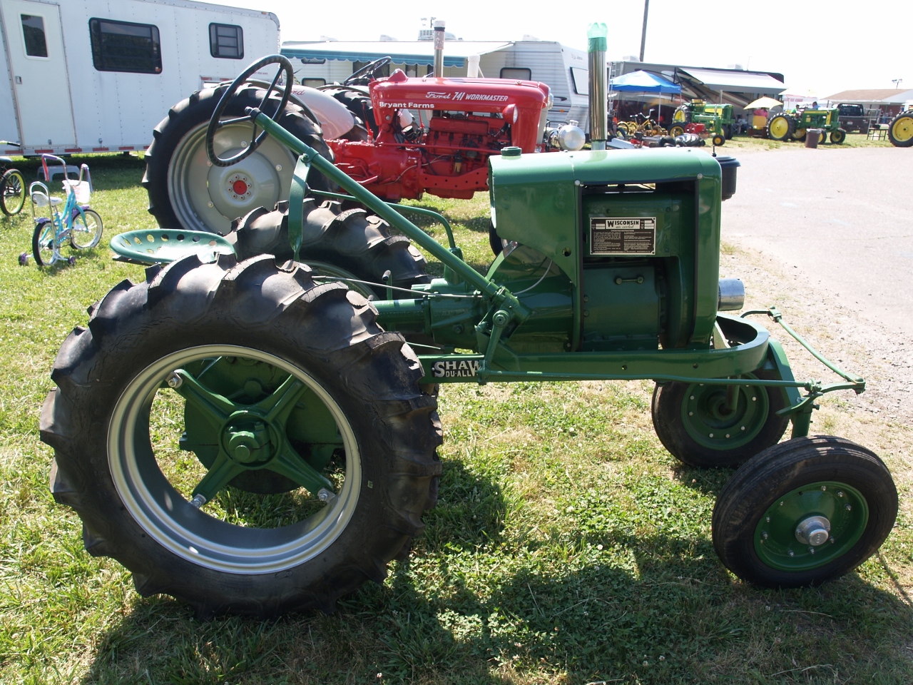
 How big is a garden anyway? At what square footage does it stop being a garden and become a farm field? That was the question posed by Shaw Manufacturing Co. in their catalog number 21. It was also the question you might ask about the R 12 Du-All because it was somewhere between a “garden tractor” and a small full size. 


Powered by a two cylinder, air cooled Wisconsin TF engine that pumped out twelve horsepower it was the top of Shaw’s line and in direct competition with tractors like Deere’s L and LA and International’s Farmall Cub. Shaw contended that their tractors could do the same jobs more economically than a full size tractor.


Catalog # 25 was published in 1953 and marked the 50th anniversary of production of gas engines and garden tractors. Gas engine production it said, had been sidelined several years previously to meet demand for the tractor products. The tractors shown in earlier catalogs were mainly walk behind  models. By 1953 they had  been replaced by riding tractors. 


The R 12, it said,could handle a 14” plow in most soil conditions. Accessories offered included: hydraulic kits, cultivators, cutter bars, disc harrows, disc plows, hauling carts and hay rakes. Lawn mowers, snow plows, bulldozer blades, planters, sprayers and end loaders were also available. 


The R12 had a wheelbase of 60 inches and was mounted on 7” by 24” rear tires, 4” X 12” in the front which gave it a 24 inch plant clearance. The transmission was described as “selective sliding gears, synchronous automotive type. Speeds ranged from 2 ½ to 7 miles per hour. It weighed in at 1150 pounds. 


By the time catalog # 21 was published, ( unfortunately they didn’t date the earlier ones ) Shaw had operations in Columbus, Ohio, New York, NY., and Chicago, Ill. as well as their factory and main office in Galesburg, Kansas. Apparently this did not last as later publications don’t mention them. 


According to Shaw, “ Many customers drive to our factory and haul our riding tractors in trailers. Some drive more than a thousand miles. One customer purchased a R 12 T tractor and drove it home across several Kansas counties, across an adjacent state and into the third state.”  Shaw’s shipping and handling charges must have been predatory. I think I would beg, borrow or steal a truck or a trailer before taking an interstate drive on a lawn tractor. 


Source:
Oldirongardentractors.files.wordpress.com  provided all the information used for this post. This is a must see website for anyone who is interested in this type of machinery. They have posted a collection of downloadable catalogs and sales literature that is the best source of information available on a variety of collectable garden tractors and are adding more all the time. 
The R 12 shown in these photos is owned by Wayne Bryant, it was exhibited at the Foothills Antique Power Association show in Hickory, NC. Visit www.foothillsantiqe.com to learn more about the upcoming 2021 show. ( That is if Gropin Joe Obidenbama doesn’t put the country in permanent lockdown as part of his Covidiocy policy. ) 
 

Sunday, November 1, 2020

Six HP Witte Engine and a Dynamo

 This post is about the known and the unknown. While what is commonly known can be interesting, the unknown usually holds a greater fascination. With that in mind, we’ll begin with what I’ve been able to learn and save the mystery for later. 


Engines bearing the Witte name were produced in one form or another for almost 100 years so it’s not too hard to locate some info about them on the web. August Witte opened a foundry in Kansas City, Missouri in 1870. His son, Edward joined the family business as an apprentice to learn the trade at an early age. When August retired in 1886 ED was ready to take command of Witte Iron works. 


In the last decades of the 19th century the internal combustion engine looked like the wave of the future so Ed, like hundreds of other industrialists, decided to catch a ride. He designed his own engine that was ready for production by 1894. It was also about this time that the company name was changed to the Witte Engine Works. 


Witte sold engines primarily by mail order. I found one of his ads in a publication called Gas Review dated January 1914. The ad copy reads,” Sold only direct from my factory to users at strictly factory prices.” That might have been the case during the early years, but as time passed Witte engines were sold globally through a network of distributors. 


Witte offered engines as portables, stationary, skidded and saw rig style. Horsepower ranged as follows, two hp for $39.45, four hp, $75.50, six hp, $99.35, eight hp, $ 149.90, eleven hp, $218.90, twenty hp, $389.50. 


You could also choose the type of fuel that your engine would run on. Kerosene, gasoline, distillate and natural gas models were available.  Best of all you were offered a sixty day free trial and your engine carried a five year guarantee. Try getting those terms at your local Greedmart. 


Ok, that was the easy part. If you want to learn more about the adventures of Witte Engine Works in later years any search engine should turn up multiple results. A good place to start would be, www.dieselworldmag.com/diesel-tractors/a-witte-pair/# . Now let’s take a closer look at the part of this rig that really grabbed my attention.


The owner, John ( didn’t mention his last name ) told me that he had been unable to learn much about this generator or dynamo during the years he has owned it. He could not find the name of the manufacturer anywhere on it. Likewise for the date when it was made but he believes it was somewhere around 1905. 


I think 1905 or earlier would be about right. I spent hours searching the web and turned up almost nothing that looked similar to this machine. I did find one drawing of an early dynamo that had a similar shaped housing but no information was provided. In addition to the Witte advertisement I also found an ad for Roth generators in Gas Review. It was one of those classified ads that you find in the back of magazines. At first I thought I had found the answer because the illustration looked somewhat like this dynamo but now I’m not so sure. It was a very low quality drawing and really could have been almost anything. 


Who made it and when remains a mystery but the electrical characteristics  are clearly stamped on a machined flat surface on the frame. Sixty amps, 7 ½ KW, 125 volts. The serial number appears to be 6154. If anyone can add some information about it, your comments would be welcome. 


Sources: 

Gas Review, Jan. 1914, page 29 
dieselworldmag.com/diesel-tractors/a-witte-pair/#  


Thursday, October 1, 2020

1929 Farmall

 When it was introduced in 1924, International Harvester presented the Farmall as the revolution in agriculture that farmers had been waiting for. The claim wasn’t all hype. The standard wide stance tractor had proven it’s worth years before at tasks like plowing and belt work. The Farmall added row crop work like planting and cultivating to the list. Mr. Farmer could now collect a tidy sum by sending Ole Dobbin to the glue factory, not to mention saving the cost and time spent mucking out processed oats and hay from his stall. 


The International Harvester catalog claimed it could: plow 7 to 8 acres per day, bed up or list 20 acres per day, plant 20 to 30 acres per day, cultivate 15 to 25 acres per day, or mow 20 to 30 acres per day. All far more than he could accomplish with the best team of horses or mules that money could buy. The three wheel design and independent  rear wheel brake system enabled it to turn within an eight foot radius making the tractor nearly as nimble as that team of horses as well.


The Farmall was shipped from the factory with a belt pulley, adjustable drawbar, removable wheel lugs, brake power takeoff and an oil air cleaner as standard equipment, It was rated for two plows and had ample belt power to run a small threshing machine or an average size ensilage cutter. 


International Harvester had long produced a catalog full of farm machinery for both horse drawn and machine powered applications that covered just about everything you could want to do. When the Farmall was introduced, they added attachments designed specially for the new tractor. The list included: two row and four row cultivators, a 7 foot mower attachment, a two row middle buster, a four row planter and a sweep rake. 


All these attachments were powered by an IH four cylinder valve in head, kerosene engine with a bore of 3 and ¾ inches and a stroke of 5 inches. The Farmall was tested at the University of Nebraska at Lincoln from September 14 th to the 19 th in 1925. Maximum horsepower on the belt was found to be 20.05, at the drawbar it was rated at 13.27 hp with  the engine turning at 1200 rpm. 


The engine was fed from a main tank that held 13 gallons of kerosene, gasoline for starting was provided by a small tank that only held ⅞ ths of a gallon of fuel. The transmission provided three forward gears with speeds of two, three and four miles per hour and a reverse that ran at 2 ½ mph. 


In 1931 International Harvester added a new variant that they named the F 30. It was basically a power upgrade from the Farmall. At this point the original version became known as the Farmall Regular. The following year saw more changes with the Regular getting a power boost by way of a new engine and being renamed the F-20. A smaller lighter tractor designated the F12 was also added and Farmall became a line of tractors, instead of a single model.  The F series continued until 1939 when it was superseded by what came to be known as the letter series tractors. 


The 1929 Farmall shown here is owned by Kevin and Jordan Isenhour. It was exhibited at the Foothills Antique Power Association of NC show at the Hickory American Legion Fairgrounds located at Newton, NC. For information about their shows visit; www.foothillsantique.com .


Sources:

International Harvester Catalogue # 27 
Digitalcommons.unl.edu  Nebraska Test # 117
En.wikipedia.org 


Tuesday, September 1, 2020

Mayrath Garden Tractor

Mayrath is best known today as a manufacturer of specialized agricultural equipment for bulk grain handling like augers and conveyors used to fill silos and bunkers. This was not always the case however. For a brief period, Mayrath also manufactured a line of garden tractors. 


Martin Mayrath established Mayrath Machinery Inc. in Dodge City, Kansas and from 1949 until 1952 built tractors that were offered in three versions.  The base model was a five horsepower, Briggs and Stratton engine mounted on a frame. According to the advertisement displayed with this tractor the transmission provided three forward speeds plus reverse. Forward speeds were two to 20 miles per hour. The price for this version was $295.


For a mere $15 more you could move up to an eight and a quarter horsepower Briggs engine. This version offered an increase in speeds from three to thirty miles per hour plus the boost in horsepower. The advertisement claimed an economical sixty miles to a gallon of gasoline.  


The Deluxe model was offered for those who only travel first class. In addition to the eight and a quarter hp engine it featured a sheet metal body and a spring mounted bench seat for two passengers. The eighty five extra dollars bought you a machine that couldn’t decide whether it was a garden tractor or a go cart. This element of confusion might explain why Mayrath tractors were only offered for three years.


Options and attachments available included the following. Power take-off with a separate clutch, $6.25. Forty-two inch sickle bar mower, $87.50. Moldboard plow attachment, $29.50. The advertisement boasts, “ mowes at five miles per hour”. That seems like a pretty fast pace for mowing to me. 


Mayrath lives on today as part of AGI Global Agricultural Products and Services Company, a multinational company that operates on six continents.  AGI Mayrath manufactures portable grain augers and conveying systems at a factory located at Clay Center, Kansas. 


Sources: 

Mayrath advertisement as shown in photos taken at the 2019 Steam Expo. 
www.tractordata.com
http://hutchinson-mayrath.com 
www.aggrowth.com 


Saturday, August 1, 2020

2 1/2 HP Aermotor

The appearance of this hit and miss engine is guaranteed to grab your attention. Even someone who’s never heard of a water hopper and couldn’t care less what one is, would likely wonder; “What is that thing?”.  When I spotted this engine at last year’s Steam Expo. I wasn’t sure it was a water hopper at all. As you can tell from these photos, the top was above my line of sight and the fins are not very wide. I thought it might be an attempt at an air cooled heat sink. Is that what they mean by the AERmotor? All that aside, the experts at Gas Engine Magazine say it’s a water hopper so a water hopper it is. 


Gas engines were a short lived sideline for the Aermotor Co. The name refers to a machine that is literally an AIR motor, more commonly known as a windmill. About 1883 a Chicago based company that manufactured dictionary stands and farm machinery hired an engineer by the name of Thomas Perry to assist with the development of a new grain binder but Perry was more interested in developing another project. Before he was hired by LaVerne Noyes he was employed by the U.S. Wind Energy Co. of Batavia, Illinois where he had done extensive testing on wind wheel design. Using what amounted to a primitive wind tunnel, he had tested 61 different wind wheel designs and had come up with a steel wind wheel that was 87% more efficient than the wooden wheels then being produced. 


Incredibly, the management at his former employment had not been interested in what Perry had developed but Noyes definitely was. Perry was given a green light to continue his work on windmills and by 1888 the Aermotor Windmill was offered for sale. Sales were lackluster that first year with a mere twenty-four windmills being sold, but by 1890 a new factory was under construction that was dedicated to production of Aermotor windmills. By 1892 an expansion of those facilities was required to meet the demand for the new “Scientific” windmill. 


If you can manufacture steel towers for windmills, towers for other applications is a natural direction for expansion. Aermotor made towers for a variety of government agencies that included the Army Corp. of Engineers, the Geodetic Survey and the Forest Service. They also produced electrical transmission towers for high voltage power lines. From the early 1900’s into the 1940’s they manufactured gas engines like this one. They also produced electric generators and water pumps but windmills always remained their primary business. 


In 1958 the company was sold to Motor Products Corporation located in Detroit, Michigan. In the years that followed the company changed ownership a number of times, including a move offshore to Argentina. In 2006 a group of ranchers in Texas bought the firm and returned production to the United States at a factory located in San Angelo, Texas where it remains today. If you’re in the market for a “Scientific” windmill visit their website at: www.aermotorwindmill.com . You won’t however be able to buy a gasoline engine like this one. 


Sources: 

www.gasenginemagazine.com Circa 1920 Aermotor 2 ½ hp general purpose engine by Glenn Thompson  Aug. / Sept. 2018 
https://aermotorwindmill.com/pages/a-history-were-proud-of 
 
Ed. Note:  The astute reader may note a difference in the appearance of this post, that's because it was done on the new and improved Blogger. Like everything that's being produced by the current "tech." industry it's a miserable CF.

Wednesday, July 1, 2020

McCormick-Deering 10-20

In production from 1923 until 1939, the 10-20 proved to be one of  International Harvester’s biggest hits. Beginning serial numbers ran from KC 501 in 1923 to KC 214 886 in 1939.  The 10-20 model was a two plow rated tractor while the 15-30 was a power upgrade for those who needed a three plow rated machine.


Designed with maximum versatility in mind, they offered belt pulley power and a direct power take off option. The 10-20 was also offered in Orchard, Narrow Tread and Industrial versions, The orchard version came equipped with: high skid rings, fenders, a short air intake pipe, low steering wheel and low seat. Options were fenders with aprons on the rear wheels, disc wheels and a spark arrestor. 


The narrow tread version had a width of only 48 inches and was designed for use on row crops that were closely spaced like hops, sugar cane and vineyards. The rear spoked wheels were 42 inches in diameter with a 12 inch face as standard. Optional were 10 inch face wheels that reduced the stance to 46 inches  


The Industrial version was targeted for industrial. commercial and construction markets wherever mobile power was needed. Customers included factories, lumber yards, sawmills. Mines, municipal and other governments. There were a number of features that set it apart from the agricultural tractor. The transmission offered speeds of 2, 4, and 10 mph forward and 3.8 mph in reverse. It came with solid disk wheels and hard rubber tires. It offered foot controlled accelerator and brakes and with a nod to creature comfort, the seat was spring mounted. An electrical system was available as an option, that consisted of : headlights, generator and battery.  


Those were the differences but the main components of the variants were basically the same. The one piece main frame was used on all models . Looking somewhat like a cast iron bathtub without the feet, it provided support and enclosed components from the radiator to the drawbar. 


The same power plant was used on the different 10-20 configurations, a four cylinder, vertical, valve in head engine that McCormick-Deering built in-house.  Measuring 4 ¼” across the bore and 5” stroke it displaced a total of 283 cubic inches.


Designed to start on gasoline, the tractor was equipped with a ¾ gallon tank. Once at operating temperature, the driver switched to the more economical kerosene supplied from the fifteen gallon fuel tank. Ignition was jump spark, supplied by high tension magnetos. Started by hand cranking, no battery was needed.


McCormick-Deering stressed ease of service and maintenance in their catalogs. The engine was equipped with standard cylinder sleeves that the farmer could replace himself,eliminating the need to rebore the cylinder for an engine overhaul. A far cry from the products of today that are designed to make user maintenance impossible. Nowadays they get you coming and going. 


One final point that I think is worth noticing is the handhold covers on the side of the engine. The catalogue says they are for inspecting the crankshaft and connecting rod bearings. This strikes me as odd. Was bearing life so short that frequent replacement was necessary or were there other reasons the owner would need to look into the crankcase? Looking at illustrations and these photos I noticed that no oil dipstick  is readily apparent. Could that have something to do with it? 


Sources:

International Harvester McCormick-Deering Line catalogues No. 27 and 35 
www.tractordata.com 
Encyclopedia of American Farm Tractors by C.H. Wendel  


Monday, June 1, 2020

The Hill Climb Challenge

There’s always something interesting to see at the Steam Expo. and the 2019 show had plenty to offer. When you buy your ticket and walk through the gate to the fairgrounds, you’re standing on a hill where you can look down on the exhibit area and decide where you want to go.  There were a couple of traction engines fired up, making steam and a lot of smoke, ( Greta would be aghast ). I knew that would be my first stop.


It seems that I had missed the first part of the story. I was told that earlier in the day a Case engine had climbed the grass slope all the way to the top and now the gauntlet was down. Never let it be said that a Case engine could best an Aultman - Taylor at anything. It was a matter of honor. 


Climbing a hill with a steam traction engine  is not the same as with a gasoline powered vehicle. If you were to assemble a team of the world’s best engineers and give them the task of designing a machine that was totally unsuited for climbing a slope, they would probably come back with something very similar to a locomotive boiler style steam engine. You have to understand what goes on inside one of these beasts to appreciate the difficulty. A cut away view of the inside of these boilers is a big help if you don’t already have an understanding. One source I found online is an illustration from a book called Farm Engines and How to Run Them by James H. Stephenson, published in 1903.  It is available at: www.gutenberg.org/files/43867/43867-h/43867-h.htm . 


Set aside the obvious, the two plus tons of the engine and the added weight of the water for the boiler. Disregard the fact that the steel wheels have no cleats because they would damage paved surfaces. Just consider what happens inside the boiler tube when the traction engine leaves a horizontal surface and begins to climb an inclined plane. 


The first effect of course is that the water in the tube runs to the lowest point, reducing the area where heat transfer can occur  and steam can be produced. Next consider that the  stack is no longer at an optimum angle to induce draft through the firebox and tubes and  out the top. As a result, the temperature begins to drop. The steam dome as well is no longer at the highest point to collect the steam and send it to the engine. All these effects begin to reduce the power available to propel the locomotive up the slope.  


In spite of these shortcomings, or maybe because of them, there is a long tradition of attempting a hill climb with one of them. I was aware of this because I had seen photos in Jack Norbeck’s  Encyclopedia of American Steam Traction Engines. On page 299 there are a couple of photos of a 12 hp Case engine climbing a ramp that was built for this purpose by the Michigan Steam Engine and Threshers Association at Mason, Michigan. These pictures were taken in the 1970’s, but while I was researching material for this post, I found a much earlier example. 


Offered for sale on Ebay was a 1908 postcard that looks to be printed from one of those hand “colorized”, black and white photographs. It shows a ramp that is almost exactly like the one in Mason and a Case engine crawling up it. A caption printed across the postcard reads “Case engine doing real hill climbing stunts.”  A banner displayed in the photograph declares,” Case engines are the only real hill climbers.” I think it’s pretty clear that Case was using these demonstrations as a publicity stunt. 


The evidence indicates that there was something to Case’s claims, but what was it that gave a Case engine an advantage? Looking for some kind of answer I turned to the only Case catalog that I have, a 1916 issue, and found exactly nothing. No mention of hill climbing or any information about boiler construction that would shed some light. Case seems to have lost interest in the subject by this point in time. 


Meanwhile, back at the Steam Expo. our Aultman-Taylor made several more attempts but never quite made it to the top. Venting might make you feel better but for now at least, Case remains King of the Hill. 


Sources:

www.gutenberg.org 
www.ebay.com/itm/case-hill-climbing-steam-engine-tractor-postcard 

For information about the 2020 show visit: www.capa-ga.com